
Great! So we’ve got everything sorted out about how our loop switcher should behave.
However, before we start writing code, we need some sort of a prototype to test it on. In this chapter I will show you how to build such a prototype (the one you can see in the video of my previous post PART 5: Defining features).
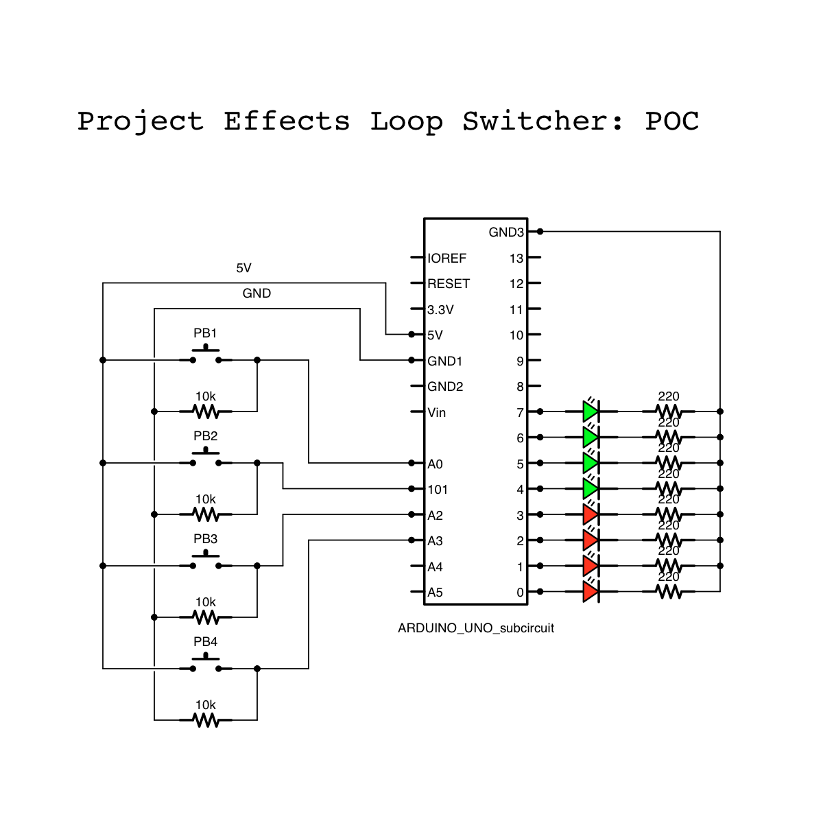
Basically the prototype will just represent different parts of what eventually will become the loop switcher and will react to the inputs according to what we define in the software code:
- At the heart we have -off course- the Arduino board itself. Later on it might be replaced by a smaller variant (Micro or Nano), but we might as well stick with this one as long as we’re not running out of space.
- Next to it we have a solderless breadboard. It is very commonly used in electrical prototyping, since you can very easily add or remove components, make connections,… . For more info, check Google.
- Green LED’s represent themselves: feedback LED’s that indicate the selected preset
- Red LED’s represent the statuses of each of the loops. They visualize the output that will eventually set the relay open (OFF) or closed (ON)
- The push buttons represent the momentary foot switches that will be used in the final product.
Below is a schematic of how all components should be hooked up:
Board setup
The setup I’m using is the one that comes with the Arduino starter kit. It contains all you need to build basic prototypes.
I have an Arduino board and a solderless breadboard placed next to it. Both are mounted on a wooden plate, also included in the starter kit. This makes for a clean setup and prevents the Arduino board and the breadboard from moving independently (which often results in connections coming off of one of the boards)
Pushbutton setup
Pushbuttons must be connected to a digital in on one side (or – in my case – an analog in, which can also be configured as a digital in) and a power source (5V) on the other side. When the button is pressed, the digital input ‘feels’ the 5V so it knows the button is pressed. In order to make it possible for the Arduino to ‘feel’ this voltage, it must be able to compare it to some kind of reference voltage, for which 0V (GND) is used. Therefore we branch off from the connection between the button and the digital in, into the GND. Now, to prevent the current from running straight into the GND instead of our digital in when the button is pressed we place a high value resistor (10kΩ) between our branch and the GND.
The result: when the button is pressed, the input feels 5V, when it is released it feels 0V (through the resistor)
LED setup
LED’s are fairly simple to set up. The most important thing when hooking up al LED is it’s polarity: since a LED is a diode it only lets current pass in one direction.
So this is basically how it goes: when set to ON, 5V goes from the digital out into the LED’s anode (the longest of the two connection pins), comes out on the kathode and goes into the GND.
HOWEVER, we need to take Ohm’s law into consideration which states that for a given voltage (U, in Volts), the current (I, in Ampères) increases when the resistance (R, in Ohms) decreases – with I reaching infinity when R reaches 0 and vice versa.
Or also:
U = I*R or U/R = I
Since the resistance of a LED is negligible, the resulting current would become far greater than what the Arduino is capable to deliver (which is about 30mA / 40mA peak).
Therefore we need to add a resistor somewhere in between the path from digital out to GND (just before or right after the LED). I chose a resistor of 220Ω to reduce the current to about 23mA
5V = I * 220Ω => I = 5V / 220Ω = 0,0227A
Finally
And this is basically all there is to it. It all comes down to wiring up all the buttons and all the LEDs. Following the above scheme will leave you with a prototype on which we can test the code that we’ll discuss in the next chapter (coming up…).