
For me the first steps into Arduino World went like a breeze. Easy peasy! So it was time to move on to some more ‘advanced’ stuff. How about a good old ‘Hello World’?
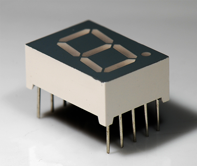
From one of my previous projects I had a seven segment digit display: basically seven LEDs (eight in fact, when you count the dot in the lower right) that are formed and arranged in a way so they can display all digits (0-9). They have 10 pins: one for each LED and 2 common pins. First you’ll have to find out which pin corresponds to which segment (or consult the datasheet). Then it comes down to applying a voltage on the segment you want to light up.
Note: there can be two types of seven segment displays. The difference lies in the way the LEDs are oriented. Since LEDs only work with current flowing in one particular direction (in the other direction they just block the current) it is important to figure out the polarity of the display’s LEDs. For some displays the common pins need to be connected to the ground (common cathode), for the other types the segment specific pins need to be connected to the ground (common anode). If you don’t know this (like me) it may take a while to figure out what on earth is going on… (display not working or inverted LED state).
Wiring it all up is pretty straightforward: since my display needs a voltage applied to the common pins, you’ll need to connect the 5V output of the arduino board to one side of a ±40 Ohm resistor (at least 0.3W) and one of the common pins to the other side.
Then connect each of the LED pins (cathodes) to the digital outs on the Arduino board that will be used to control the LED states.

Note: since we have a common anode, this means that the segments will light up only when the corresponding digital outs on the Arduino board are set to LOW.
Once all this is set up, it is time for some C programming. Don’t worry since the features on the Arduino are really understandable, most of the programming functions are so too.
Now open the Arduino software, start a new ‘sketch’ (the Arduino name for a program) and complete the following steps:
Set up the variables
First I define the variables that are used in the sketch.
int h[6] = {5, 1, 2, 4, 5, 7};
int e[6] = {5, 3, 4, 5, 6, 7};
int l[4] = {3, 4, 6, 7};
int o[7] = {6, 1, 2, 3, 4, 6, 7};
int timeBetweenLetters = 100;
int timeBetweenLoop = 1000;
Since I want to display different characters, I create arrays that contain the numbers of the digital pins that will be used to light up the corresponding LED’s for the specific character. For convenience I name the arrays after the characters they will display (h, e, l, o). Also I added a first element to each array that indicates the number of LED’s that are lit (which is the length of the array – 1). This is to avoid having to count the length of the array.
The other two variables are timeBetweenLetters and timeBetweenLoop. They define the time between each letter (in milliseconds) and the time between each loop.
Set up the board
Each Arduino sketch needs a setup() function. Inside this function the board is set up. A common thing to set here is the function of the digital pins. They can be defined either as input OR as output using the function pinMode().
I will set up 8 pins as outputs to control the segments of the display. Since it is a repetitive instruction I put this in a loop in a separate function, called setPins().
void setPins() {
  for (int i = 0; i < 8; i++) {
    pinMode(i, OUTPUT);
  }
}
Then I call this function in the setup() function.
void setup() {
  setPins();
}
Adding behaviour
When an Arduino program is running on the board, it is actually running the same the same logic loop over and over again at a huge rate (depending on the complexity of the program). Inside this loop there can be checks to make the Arduino ‘brains’ decide on what to do next. The loop logic is located inside the function loop().
void loop() {

  // logic (commands, checks, function calls) goes here.

}
For my sketch I need 2 main features: clear the display and display a specific character. Hence I created 2 functions that can take care of this:
void clearDisplay() {
  for (int i = 0; i < 8; i++) {
    digitalWrite(i, HIGH);
    delay(30);
  }
}
ClearDisplay() loops through all the pins and sets them to HIGH, which makes the LED’s dim (remember the ‘common anode’ wiring). The delay of 30 ms is just to get a specific visual effect.
The next function shows a specific character and is called setDisplay():
void setDisplay(int numVal[]) {
  clearDisplay();

  delay(timeBetweenLetters);

  for (int j = 1; j <= numVal[0]; j++) {
    digitalWrite(numVal[j], LOW);
    delay(1);
  }
}
Basically it first clears the display, waits the time that is defined in timeBetweenLetters and finally loops through the array numVal (which will be one of the arrays that are defined in the beginning of the sketch) to set specific output pins to LOW. The function used to do this is digitalWrite([pinNumber], [HIGH/LOW]).
All this combined results in a loop function like so:
void loop() {
   setDisplay(h);
   delay(timeBetweenLetters);
   setDisplay(e);
   delay(timeBetweenLetters);
   setDisplay(l);
   delay(timeBetweenLetters);
   setDisplay(l);
   delay(timeBetweenLetters);
   setDisplay(o);
   delay(timeBetweenLetters*3);
   clearDisplay();
   delay(timeBetweenLoop);
}
The complete sketch
When you put all this in one sketch, it should look something like this:
int h[6] = {5, 1, 2, 4, 5, 7};
int e[6] = {5, 3, 4, 5, 6, 7};
int l[4] = {3, 4, 6, 7};
int o[7] = {6, 1, 2, 3, 4, 6, 7};
int timeBetweenLetters = 100;
int timeBetweenLoop = 1000;
void setup() {
   // initialize the digital pins as outputs.
   setPins();
}
void loop() {
   setDisplay(h);
   delay(timeBetweenLetters);
   setDisplay(e);
   delay(timeBetweenLetters);
   setDisplay(l);
   delay(timeBetweenLetters);
   setDisplay(l);
   delay(timeBetweenLetters);
   setDisplay(o);
   delay(timeBetweenLetters*3);
   clearDisplay();
   delay(timeBetweenLoop);
}
void setPins() {
   for (int i = 0; i < 8; i++) {
     pinMode(i, OUTPUT);
   }
}
void setDisplay(int numVal[]) {
   clearDisplay();

   delay(timeBetweenLetters);
   for (int j = 1; j <= numVal[0]; j++) {
     digitalWrite(numVal[j], LOW);
     delay(1);
   }
}
void clearDisplay() {
   for (int i = 0; i < 8; i++) {
     digitalWrite(i, HIGH);
     delay(30);
   }
}
Uploading your sketch
All you have to do now is to compile your sketch into bytecode and to upload this bytecode onto the Aduino board.
The Arduino website has a complete section about how to set everything up (Getting started), so if you are new to all this it might be worth checking out.
Once everything is hooked up correctly it’s only just a matter of pressing the ‘Upload’ button in the code editor and to wait until it shows the message ‘Upload complete’.
Then immediately you should see the letters H-E-L-L-O appear on the seven segment display one after the other, time after time, after time, after time,…